PERFECTRAIL
Genuine & Premium Aftermarket Land Rover Parts Specialist | Engineering Technical Whitepaper
Valvetrain Tribology
Land Rover & Range Rover
B2B Supply Chain
Land Rover Valve Tappets & Hydraulic Lash Adjusters: Comprehensive Engineering, Failure Forensics, and B2B Wholesale Sourcing Guide
Executive Lede
The Critical Micro-Hydraulic Nexus in Modern JLR Powertrains
In high-output Land Rover and Range Rover internal combustion engines, the valve tappet—operating either as an integrated hydraulic lash adjuster (HLA) within stationary roller finger follower (RFF) assemblies or as a precision-calibrated mechanical bucket tappet—represents the critical tribological interface between the revolving camshaft lobe profile and the intake/exhaust valve stem. Responsible for transmitting millions of dynamic impact cycles per hour while maintaining zero operational lash across ambient thermal extremes (-40°C to +150°C), a deviation of merely ±0.005 mm in hydraulic leak-down clearance or a microscopic varnish accumulation can precipitate severe valvetrain noise, power loss, increased tailpipe emissions, or catastrophic rocker arm dislodgement.
For automotive parts distributors, engine remanufacturers, and fleet service operators, securing an uncompromised, IATF 16949-certified supply chain for Land Rover replacement tappets is paramount to eliminating warranty returns and safeguarding engine longevity. This technical guide synthesizes industry-standard valvetrain methodologies—benchmarking established engineering standards from INA/Schaeffler Valvetrain Systems, Federal-Mogul/Sealed Power Service Protocols, and Engine Builder Magazine Valvetrain Forensics—to deliver an exhaustive reference on hydrodynamic mechanics, platform-specific failure modes, precision lash measurement, and commercial bulk sourcing from PERFECTRAIL.
Section 1
Fundamentals of Automotive Valve Tappets: Hydrodynamic Operating Principles
In the internal combustion engine valvetrain, the valve tappet (historically referred to as a cam lifter, cam follower, or lash adjuster) functions as the primary kinematic transmitter between the rotating profile of the camshaft and the reciprocating poppet valve assembly. While the mechanical objective—opening and closing the intake and exhaust ports at precisely metered crank-angle intervals—is conceptually straightforward, the hydrodynamic and tribological environments within modern dual-overhead camshaft (DOHC) engines require extreme precision.
1.1 The Hydrodynamic Force Transmission Mechanism
Automotive hydraulic tappets utilize engine oil pressure as a virtually non-compressible fluid column contained within a microscopic, pressure-sealed internal chamber. As established by classical valvetrain engineering principles synthesized across leading technical documentation (such as the INA/Schaeffler Valvetrain Systems Manual), a modern hydraulic lash adjuster operates via a continuous, cyclic four-phase hydrodynamic sequence:
The Four-Phase Hydraulic Compensation Cycle:
- Phase 1: Base-Circle Rest & Hydraulic Replenishment: When the camshaft lobe rotates away and the rocker arm or tappet face rests on the camshaft base circle (the dwell period), the external valve spring holds the poppet valve firmly closed against its seat in the cylinder head. During this period, an internal plunger return spring expands the tappet assembly outward, eliminating all physical lash across the valvetrain. Engine oil at regulated gallery pressure (typically 1.5 to 4.5 bar) enters the low-pressure supply chamber through calibrated oil feed ports, pushing open a one-way check ball to replenish the high-pressure chamber.
- Phase 2: Lobe Ramp & Check Valve Instant Sealing: As the camshaft lobe rotates into the opening ramp, increasing axial force is exerted downward upon the tappet. The sudden pressure surge within the high-pressure chamber instantly drives the check ball against its precision-ground seat, trapping a calibrated volume of hydraulic fluid within the chamber.
- Phase 3: Solid Hydraulic Column Valve Actuation: With the check valve sealed, the trapped oil behaves as a rigid hydraulic column. The mechanical lift from the camshaft lobe is transmitted with virtually zero deflection directly through the rocker arm or bucket directly to the valve stem tip, compressing the valve spring and opening the combustion chamber port.
- Phase 4: Controlled Leak-Down & Thermal Equilibrium: During the peak valve lift event, extreme cylinder pressures and valve spring resistance generate internal hydraulic pressures exceeding 100 bar. A microscopic, engineered leak-down occurs through the controlled annular clearance between the inner plunger and outer cylinder housing (measured in microns). This minute oil leakage allows the lifter to automatically adjust its operational length, compensating for thermal expansion of the valve stem as the combustion chamber heats up, preventing valve seat burning or incomplete seating.
1.2 Valvetrain Tribology and Contact Stress Dynamics
The contact interface between the camshaft lobe and the tappet surface endures some of the highest localized Hertzian contact stresses found anywhere in an internal combustion powertrain, often exceeding 800 to 1,200 MPa. In direct-acting mechanical bucket designs, sliding boundary friction dominates, necessitating extreme surface hardness and advanced low-friction coatings. In modern Land Rover roller finger follower (RFF) architectures, the tappet serves as a stationary hydraulic pivot post supporting the rocker arm, transferring sliding friction to rolling friction at the camshaft interface while bearing continuous pulsating pivot loads.
Key Engineering Takeaway for B2B Parts Buyers:
The operational integrity of a valve tappet is governed by fluid mechanics and metallurgy. Substandard aftermarket tappets with improper annular plunger clearances suffer from uncontrolled leak-down rates, leading to severe valvetrain clatter at cold start and catastrophic valve float at elevated engine speeds.
1.3 Elastohydrodynamic Film Thickness & Stribeck Curve Analysis
Understanding the hydrodynamic lubrication regime requires analyzing the minimum oil film thickness (hmin) governed by the Dowson-Higginson formulation for line contact:
Where R’ represents the effective reduced radius of curvature between the camshaft profile and tappet face, U denotes the dimensionless entrainment speed parameter, G is the dimensionless material property parameter (accounting for the pressure-viscosity coefficient of Land Rover synthetic lubricants), and W represents the dimensionless normal load parameter. Under cold-start conditions or sustained high-RPM operation, if the viscosity parameter drops significantly due to thermal shear, the dimensionless film thickness parameter Λ = hmin / √(Rqcam2 + Rqtappet2) decreases below 1.0. In this critical regime, the valvetrain operates entirely in boundary friction, leading to direct metal-to-metal micro-welding and accelerated cam lobe scuffing unless high-lubricity surface treatments are applied.
Section 2
Hydraulic Lash Adjusters (HLA) vs. Mechanical Solid Bucket Tappets: Engineering Comparison
Powertrain engineers select between Hydraulic Lash Adjusters (HLA) and Mechanical Solid Bucket Tappets based on target RPM ceilings, reciprocating valvetrain mass, acoustic NVH (Noise, Vibration, and Harshness) requirements, and maintenance lifecycle profiles. Understanding the engineering tradeoffs between these two distinct technologies is vital for automotive distributors and engine rebuilders when recommending replacements for Land Rover applications.
| Engineering Parameter | Hydraulic Lash Adjuster (HLA / Hydraulic Lifter) | Mechanical Solid Bucket Tappet (Solid Lifter) |
|---|---|---|
| Lash Maintenance | Zero-maintenance; automatic hydraulic compensation across all thermal cycles. | Manual adjustment via calibrated interchangeable shims or graded base thickness. |
| Max Operating RPM Limit | Moderate (typically ≤ 6,800 RPM) due to potential hydraulic pump-up or valve float. | High (8,500+ RPM); rigid mechanical interface eliminates hydraulic compressibility. |
| Acoustic NVH Signature | Extremely quiet; zero mechanical clearance prevents metallic contact clicking. | Moderate acoustic tapping during cold-start lash expansion clearance gap. |
| Sensitivity to Oil Quality | Very High; sensitive to oil aeration, viscosity breakdown, and particulate sludge. | Low; requires only boundary hydrodynamic lubrication film on cam contact face. |
| Reciprocating Mass | Heavier internal assembly (body, plunger, check valve, spring, and hydraulic fluid). | Lightweight single-piece forged steel or precision alloy construction. |
| Typical JLR Applications | 2.7L / 3.0L TDV6/SDV6 (276DT, 306DT), Ingenium 2.0L Diesel/Petrol (AJ200). | High-performance AJ133 5.0L Supercharged V8 / AJ126 3.0L Supercharged V6. |
2.1 Hydraulic Pump-Up vs. Collapse Dynamics
Two critical failure thresholds govern hydraulic lifter operation under high-stress conditions:
- Hydraulic Pump-Up: Occurs when engine speed exceeds the spring’s ability to maintain valve control (valve float). During the floating phase, the HLA plunger spring expands to fill the false lash gap. When the valve returns to its seat, the over-expanded lifter prevents full valve seating, resulting in immediate compression loss, backfiring, and potential piston-to-valve mechanical collision.
- Hydraulic Collapse: Occurs when oil aeration (foaming), low oil pressure, or high-temperature viscosity shear allows fluid to escape the high-pressure chamber faster than the leak-down replenishment rate. The collapsed lifter produces excessive clearance, leading to high-impact valve seating, reduced effective valve lift, and severe valvetrain noise.
2.2 Roller Finger Follower (RFF) Stationary Pivot Elements
Modern Land Rover diesel and petrol platforms predominantly employ stationary hydraulic lash adjusters mounted into the cylinder head casting. The hydraulic element acts as a fixed hydraulic pivot for a stamped or forged steel rocker arm equipped with a needle-bearing roller follower. This configuration isolates the hydraulic lifter from reciprocating valvetrain mass, significantly reducing inertia while enabling zero-lash acoustic refinement.
Section 3
Land Rover Valvetrain Architectures: TDV6, Ingenium, and AJ133 In-Depth Analysis
Jaguar Land Rover (JLR) has deployed diverse valvetrain architectures across its luxury SUV portfolio—including Discovery, Range Rover Sport, Range Rover Vogue, Defender, and Evoque. Each platform presents unique hydrodynamic, mechanical, and thermal challenges for the valve tappet assembly.
3.1 JLR 2.7L & 3.0L TDV6 / SDV6 (276DT / 306DT) Valvetrain
The 2.7-liter and 3.0-liter twin-turbocharged V6 diesel engines utilize a dual-overhead camshaft configuration per cylinder bank, with the exhaust camshaft driven by the primary timing belt and the intake camshaft synchronized via a secondary internal timing chain.
- Tappet Configuration: 24 stationary hydraulic lash adjusters (OE Reference: 1336545 / C2C21308) paired with roller rocker arms (OE: 1336544).
- Cylinder Head Oil Circuit: Oil is routed through restrictive oil control restrictors in the cylinder head deck. Extended 20,000+ km service intervals lead to soot agglomeration and thermal oil breakdown, starving the rear bank lifters (#3 and #6 cylinders) of adequate hydraulic replenishment pressure.
- Known Failure Pattern: Depleted hydraulic pressure causes the rocker arm to oscillate violently, often popping off its hydraulic pivot ball and fracturing the camshaft bearing cap.
3.2 JLR Ingenium 2.0L Diesel & Petrol (AJ200 Architecture)
The modular JLR Ingenium 4-cylinder and 6-cylinder family incorporates ultra-low friction roller bearings on the camshaft journals and advanced variable valve timing (VVT) with electro-hydraulic variable valve lift (UniAir) on select petrol variants.
- Tappet Configuration: 16 compact stationary hydraulic pivot elements (OE Reference: LR073809 / AJ813393) engineered for 0W-20 ultra-low viscosity synthetic lubricants (STJLR.51.5122 / STJLR.03.5006).
- Micro-Orifice Sensitivity: The internal check valve orifices are reduced to less than 1.0 mm to accommodate ultra-thin oils. Any particulate contamination or timing chain guide plastic debris instantly clogs the internal filtration screens, causing rapid lifter collapse.
3.3 JLR AJ133 5.0L Supercharged V8 & AJ126 3.0L Supercharged V6
The high-performance AJ133 5.0L V8 and AJ126 3.0L V6 engines employ dual independent Camshaft Torque Actuated (CTA) variable cam phasers capable of rapid cam timing shifts under high supercharger boost pressures (OE Reference: LR010775 / AJ811181).
- Severe Pressure Cycles: Peak cylinder pressures exceed 130 bar during full-boost wide-open throttle events, placing extraordinary cyclic fatigue on the hydraulic lash adjuster retaining caps.
- Metallurgical Demands: Requires premium case-hardened alloy steels (such as 16MnCr5 or 20CrMo) with Diamond-Like Carbon (DLC) coated contact surfaces to prevent scuffing against high-lift camshaft lobes.
3.4 Hydraulic Gallery Fluid Dynamics in JLR TDV6/SDV6 (276DT / 306DT)
In the Land Rover 2.7L and 3.0L V6 diesel powertrains, oil delivery to the cylinder heads is modulated through an internal gallery restrictor orifice (nominal diameter: 1.20 mm). The oil supply must satisfy two competing demands: maintaining continuous hydrostatic pressure (minimum 1.8 bar at 2,000 RPM) across 24 stationary hydraulic lash adjusters while feeding the camshaft plain journal bearings.
During cold engine start-up in sub-zero climates (-20°C), high lubricant viscosity delays hydraulic pressurization to the rear cylinders (#3 on Bank 1 and #6 on Bank 2) by up to 4.5 seconds. If the HLA leak-down rate is improperly calibrated, the hydraulic plunger collapses completely during these unpressurized cycles, creating an instantaneous 0.8 mm lash gap. When the camshaft lobe impacts the rocker arm roller follower, the dynamic shock load spikes to over 3,500 N, rapidly fatiguing the aluminum camshaft bearing cap fasteners and precipitating valvetrain failure.
3.5 JLR Ingenium AJ200 Electro-Hydraulic UniAir Variable Lift Interface
On petrol variants of the JLR Ingenium 2.0L architecture (AJ200P), the intake valvetrain integrates an electro-hydraulic variable valve actuation system. In this advanced configuration, the stationary hydraulic lash adjusters operate in close synchronization with high-speed solenoid-actuated hydraulic pumping chambers. The hydraulic lash adjusters must maintain a stable zero-lash datum point within ±0.015 mm to ensure the variable valve lift algorithm delivers precise cylinder-to-cylinder air mass balancing. Any internal check-valve hysteresis or aeration within the HLA directly causes erratic idle, cylinder balance faults (DTC P0300/P0316), and degraded combustion efficiency.
Section 4
Precision Lash Measurement & Camshaft Base-Circle Alignment Protocols
Achieving precise valvetrain alignment requires strict adherence to standardized measurement methodologies. When rebuilding Land Rover cylinder heads or diagnosing persistent valvetrain rattle, engine builders must verify both static installed height and dynamic leak-down rates according to professional engine rebuilding standards.
4.1 Camshaft Base-Circle Positioning and Dial Indicator Measurement
To measure mechanical clearance or verify hydraulic lifter pre-load travel:
- True Base-Circle Indexing: Rotate the crankshaft in its normal direction of rotation until the camshaft lobe heel (true base circle, 180° opposite peak lift) is perpendicular to the roller follower or tappet contact face. Never measure lash on the opening or closing clearance ramps.
- Dial Gauge Rigging: Mount a magnetic-base dial test indicator (DTI) with 0.001 mm resolution directly to the cylinder head casting, aligning the indicator probe parallel to the valve stem axis resting on the valve spring retainer or rocker arm tip.
- Plunger Pre-Load Verification: For hydraulic lifters, measure the total travel from zero-lash contact to fully compressed bottomed-out position. The optimal hydraulic pre-load for JLR engines is typically 1.20 mm to 1.80 mm (approximately 50% of total available plunger travel).
4.2 Hydraulic Leak-Down Testing Apparatus & Bench Calibration
Bench testing of replacement hydraulic tappets separates premium OEM-grade components from defective aftermarket copies. Bench testing protocols conform to the Federal-Mogul/Sealed Power Service Standard:
Standard Hydraulic Leak-Down Test Specification:
- Test Fluid: Calibrated calibration fluid or SAE 20 test oil at controlled temperature of 21°C ± 2°C (70°F).
- Applied Load: Constant axial load of 220 N (50 lbf) applied to the lifter pushrod socket/plunger cap.
- Measurement Interval: Time required for the plunger to compress exactly 1.50 mm (0.060 inches).
- Acceptable Specification: 12 to 45 seconds. A leak-down time under 10 seconds indicates excessive annular clearance (noisy collapse); a time over 60 seconds indicates tight plunger seizure (risk of valve hanging and burning).
Section 5
Root Cause Failure Diagnostics: The 7 Deadly Tappet Failure Modes
Synthesizing failure forensics from Engine Builder Magazine and real-world Land Rover warranty investigations, valvetrain failures can be systematically traced to 7 root metallurgical, hydraulic, and operational failure modes.
1. Oil Aeration, Foaming, and Hydraulic Sponge Phenomenon
Mechanism: When crankcase oil levels are excessively high (crankshaft counterweight splashing) or excessively low (oil pump pickup sucking air), micro-bubbles are entrained in the engine oil. Unlike liquid oil, air bubbles are highly compressible.
Diagnostic Signature: Audible valvetrain ticking that fluctuates directly with engine RPM and oil temperature; oil pressure gauge reads normal, but HLA plungers collapse spongy under hand pressure.
2. Thermal Varnish Accumulation and Plunger Seizure
Mechanism: Thermal oxidation of engine oil at sustained temperatures above 130°C forms golden/brown polymeric lacquer films. With internal plunger-to-body clearances measured at 0.003 mm to 0.006 mm, a 0.002 mm varnish layer causes the inner plunger to seize in its bore.
Diagnostic Signature: Plunger locked solid; unable to compress or expand; severe cold-start metallic clatter that fails to silence even after warm-up.
3. Particulate Contamination and Ball Check Valve Debris Wedging
Mechanism: Microscopic carbon flakes, metallic machining swarf, or fragmented timing chain guide plastic bypass the oil filter and enter the lifter inlet port. Debris lodges between the ceramic/steel check ball and its precision conical seat.
Diagnostic Signature: Instant loss of hydraulic lock; high-pressure chamber cannot hold pressure, resulting in total lifter collapse and zero effective valve lift.
4. Hertzian Surface Fatigue, Cam Lobe Scuffing, and Spalling
Mechanism: Occurs when core metallurgical hardness falls below 58 HRC or surface roughness exceeds Ra 0.15 μm. Microscopic surface asperities weld under boundary lubrication, tearing metal fragments from the tappet face and camshaft lobe.
Diagnostic Signature: Pitting, micro-cratering, and visible dish wear on the tappet contact crown; fine ferrous metallic flakes in the oil filter pleats.
5. Cylinder Head Gallery Sludge Blockage and Oil Starvation
Mechanism: Soot loading in diesel DPF regeneration cycles dilutes engine oil with unburned diesel fuel, destabilizing dispersant additives and depositing heavy black sludge in the dead-end cylinder head lifter galleys.
Diagnostic Signature: Multiple lifters on a single cylinder bank collapsing simultaneously; localized bluing from extreme dry friction heat on the rocker arm pivot sockets.
6. Hydraulic Pump-Up and High-RPM Valve Float Collision
Mechanism: High engine speeds paired with weak or fatigued valve springs allow the valve to separate from the cam profile. The lifter internal spring immediately expands the plunger. Upon closing, the elongated lifter holds the valve off its seat.
Diagnostic Signature: Sudden engine misfire at peak RPM; cylinder compression drops to 0 bar; physical contact witness marks on the piston crown valve pockets.
7. Rocker Arm Pivot Dislodgement and Cam Tower Fracture (TDV6 Specific)
Mechanism: Unique to JLR TDV6/SDV6 engines when a collapsed hydraulic tappet allows excessive lash gap. The stamped rocker arm (1336544) undergoes violent lateral kickback, slipping off the hydraulic pivot ball and wedging against the camshaft lobe.
Diagnostic Signature: Cast aluminum camshaft carrier cap cracked or sheared off; bent intake/exhaust valves; total loss of cylinder compression.
5.2 Metallurgical Failure Analysis & SEM Micrography
Scanning Electron Microscopy (SEM) and Energy-Dispersive X-Ray Spectroscopy (EDS) of failed Land Rover valve tappets reveal distinct fracture and surface degradation mechanisms:
- Sub-Surface Micro-Pitting: Cyclic Hertzian shear stresses peak at a depth of 0.12 mm to 0.18 mm beneath the contact surface. In tappets with inadequate core case depth (below 0.8 mm), micro-cracks initiate at non-metallic manganese sulfide (MnS) inclusions and propagate upward to the surface, causing macroscopic spalling flakes.
- Fretting Corrosion in Stationary HLA Bores: Micro-motion (oscillation amplitudes < 25 μm) between the outer HLA housing and the aluminum cylinder head bore produces black iron-aluminum oxide debris (tribo-oxidation). This debris wedges into the oil feed annulus, strangling hydraulic replenishment.
- Check Ball Seat Erosion: High-velocity oil backflow during initial valve opening acceleration erodes inferior unhardened check valve seats, widening the effective sealing diameter and causing exponential increases in dynamic leak-down rates.
Section 6
Professional Installation & Pre-Priming Protocols for Engine Builders
Improper installation and failure to pre-prime hydraulic tappets are responsible for over 65% of premature warranty claims and customer complaints regarding post-overhaul valvetrain noise. Engine rebuilders must execute a strict 5-stage pre-priming and installation sequence.
The 5-Stage Standard Operating Procedure (SOP) for Tappet Installation:
Clean cylinder head tappet bores with non-chlorinated solvent and a non-abrasive nylon bore brush. Measure bore inside diameter (ID) using an internal bore micrometer to ensure clearance to tappet outside diameter (OD) does not exceed 0.025 mm to 0.040 mm. Blow out all oil supply feed galleys with filtered compressed air (6 bar).
Submerge all new hydraulic lifters upright in a clean container filled with genuine Land Rover specification synthetic engine oil (5W-30 or 0W-20). Using a smooth brass push-tool, gently depress the inner check ball through the top oil inlet orifice while stroking the plunger. Continue pumping until air bubbles cease rising and the plunger becomes completely rigid with zero sponginess.
Liberally coat the exterior tappet body, cylinder head bore, rocker arm pivot socket, and roller follower bearing with an extreme-pressure (EP) zinc/molybdenum assembly paste (minimum 1,200 ppm ZDDP content). Never install dry or with light spray penetrating lubricants.
Install camshaft bearing caps and torque fasteners in a cross-pattern sequence to factory specification (typically 9.5 to 11.0 Nm on JLR alloy heads). MANDATORY: Allow a minimum 30-minute hydraulic settling window before rotating the engine crankshaft to allow pressurized tappets to bleed down to their equilibrium operating pre-load height, preventing valve-to-piston contact.
Before starting a rebuilt engine, connect an external pressurized oil priming tank (3.0 bar) to the main oil galley port or disable fuel injection and crank the engine in 15-second intervals until a continuous flow of oil emerges from all rocker arm and tappet weep holes.
Section 7
Metallurgical Engineering & IATF 16949 Quality Verification
At PERFECTRAIL, valve tappet manufacturing adheres strictly to IATF 16949:2016 and ISO 9001:2015 international automotive quality management systems. Every manufacturing phase—from raw alloy bar stock selection to final automated optical inspection—is engineered for extreme durability under severe Land Rover operating conditions.
Core Alloy Steel Induction Hardening
Forged from premium 16MnCr5 / 20CrMo alloy structural steel, undergoing controlled atmosphere induction case hardening with a continuous case depth of 0.8 mm to 1.2 mm, providing exceptional fatigue strength and resistance to contact pounding.
Superfinished Contact Surfaces
Precision CNC micro-lapping and superfinishing on all external cylindrical body walls and spherical pivot balls ensures ultra-smooth boundary hydrodynamic lubrication films, preventing bore scuffing and friction loss.
100% Automated Optical CMM Inspection
100% automated laser and coordinate measuring machine (CMM) dimensional verification ensures flawless plunger-to-cylinder clearance matching, guaranteeing perfectly consistent leak-down rates across every single unit.
7.2 Chemical Composition & Spectrometric Material Verification
PERFECTRAIL enforces rigorous optical emission spectrometry (OES) chemical analysis on every heat batch of raw alloy steel before precision cold-heading and CNC machining:
| Element | Specified Range (16MnCr5) | PERFECTRAIL Target % | Metallurgical Purpose |
|---|---|---|---|
| Carbon (C) | 0.14 – 0.19 % | 0.165 % | Ensures optimal core toughness while enabling high case hardness post-carburizing. |
| Chromium (Cr) | 0.80 – 1.10 % | 0.950 % | Enhances hardenability and corrosion resistance in hot engine oil environments. |
| Manganese (Mn) | 1.00 – 1.30 % | 1.150 % | Improves tensile yield strength and depth of hardness penetration during quenching. |
| Phosphorus / Sulfur (P/S) | ≤ 0.025 % Max | ≤ 0.012 % | Ultra-low impurity control prevents micro-cleavage crack initiation under cyclic fatigue. |
Section 8
PERFECTRAIL Land Rover Valve Tappet Catalog & OEM Cross-Reference
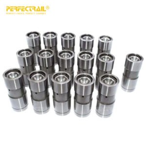
PERFECTRAIL maintains an extensive, ready-to-ship inventory of OEM and high-precision aftermarket valve tappets, hydraulic lash adjusters, and companion valvetrain kits covering all major Land Rover and Range Rover applications.
| PERFECTRAIL SKU | Land Rover OE Part # | Engine Application | Land Rover Vehicle Fitment | Type & Qty / Engine |
|---|---|---|---|---|
| PR-VT-1336545 | 1336545 / C2C21308 | 2.7L TDV6 / 3.0L SDV6 (276DT / 306DT) | Discovery 3/4/5, Range Rover Sport, Range Rover L405 | Hydraulic HLA (24 pcs/set) |
| PR-VT-LR073809 | LR073809 / AJ813393 | Ingenium 2.0L Diesel (AJ200D / 204DTD) | Discovery Sport, Evoque, Velar, Defender 90/110 | Hydraulic HLA (16 pcs/set) |
| PR-VT-LR010775 | LR010775 / AJ811181 | AJ133 5.0L V8 & AJ126 3.0L V6 Supercharged | Range Rover Sport SVR, Vogue L405, Defender V8 | Precision Tappet (32/24 pcs/set) |
| PR-VT-LHG100150 | LHG100150 / ERR3421 | Rover V8 4.0L / 4.6L & 300Tdi 2.5L | Defender Classic, Discovery 1/2, Range Rover Classic | Hydraulic Flat Tappet (16/8 pcs) |
| PR-VK-TDV6-FULL | 1336545-KIT | TDV6 / SDV6 Master Valvetrain Overhaul Kit | Discovery 4/5, Range Rover Sport | 24 Tappets + 24 Rockers (1336544) |
Looking for full valvetrain rebuild packages? PERFECTRAIL supplies consolidated overhaul kits including matched hydraulic tappets, roller rocker arms, high-strength camshafts, timing chains, and cylinder head gasket sets. Explore our Genuine & Aftermarket Land Rover Parts Supply Capabilities.
Section 9
Technical & Engineering FAQ (Frequently Asked Questions)
Authoritative technical answers to high-frequency engineering, maintenance, and sourcing inquiries from global automotive wholesalers and Land Rover master technicians:
Q1: What is the primary difference between hydraulic lash adjusters (HLA) and mechanical solid bucket tappets in Land Rover engines?
A: Hydraulic Lash Adjusters (HLA), utilized in platforms such as the JLR 2.7L/3.0L TDV6/SDV6 and Ingenium 2.0L series, rely on pressurized engine oil entering a high-pressure chamber through a ball check valve to dynamically maintain zero valvetrain clearance across thermal cycles. In contrast, mechanical solid bucket tappets employ direct cam-to-bucket contact with calibrated shim thicknesses or graded base heights, requiring manual physical lash measurement without internal hydraulic dampening.
Q2: Why do JLR TDV6/SDV6 (2.7L & 3.0L) engines frequently suffer from valvetrain tick and premature tappet wear?
A: The primary root causes include oil aeration and extended drain intervals leading to high-temperature sludge accumulation, which blocks the 1.2 mm oil feed orifices in the cylinder head lifter galleys. When aerated oil enters the HLA plunger chamber, its compressibility prevents the internal pressure chamber from supporting the valve opening load, causing the plunger to collapse, resulting in boundary friction, harsh contact stress against the rocker arm pivot socket, and audible top-end valvetrain chatter.
Q3: How does PERFECTRAIL verify the metallurgical and dimensional precision of aftermarket Land Rover tappets?
A: PERFECTRAIL manufactures valve tappets strictly under IATF 16949:2016 quality systems. Each batch undergoes 100% automated optical coordinate measuring machine (CMM) dimensional verification with diameter tolerances held to ±0.002 mm, surface roughness controlled to Ra ≤ 0.08 μm, core alloy steel induction hardening to 58–62 HRC, and proprietary Diamond-Like Carbon (DLC) or nitrided surface coatings for extreme anti-scuffing protection.
Q4: What pre-installation priming protocol is mandatory for Land Rover hydraulic tappets before engine startup?
A: Hydraulic tappets must be submerged in clean, recommended viscosity synthetic engine oil (e.g., 5W-30 or 0W-20 JLR spec) and evacuated of trapped air using a soft brass or nylon push-tool against the check valve until firm resistance is achieved with zero spongy travel. Never install dry HLAs, and never hammer or force a collapsed hydraulic element into the cylinder head bore.
Q5: What are PERFECTRAIL’s B2B supply terms, minimum order quantities (MOQs), and export packaging standards for global wholesalers?
A: PERFECTRAIL supports global B2B automotive distributors, specialized Land Rover workshops, and engine remanufacturers with flexible MOQs starting at 50 to 100 engine sets (or customized SKU assortments). Every component is preserved with VCI anti-corrosion barrier oil, sealed in airtight blister packaging, and boxed in reinforced export-grade master cartons with full OEM cross-referencing and traceability barcodes.
Section 10 • Commercial Partnership
B2B Wholesale Procurement, Custom Packaging, & Global Supply Chain Services
As an established tier-1 level aftermarket supplier and specialized Land Rover parts partner, PERFECTRAIL empowers international automotive distributors, regional wholesalers, commercial fleet operators, and professional engine remanufacturing facilities with direct-from-factory pricing, certified IATF 16949 quality assurance, and seamless global logistics.
Flexible Commercial MOQs
Low barrier entry with minimum order quantities starting from 50 to 100 engine sets. Mixed-SKU container consolidation available across complete Land Rover engine valvetrain lines.
Private Label & Custom Packaging
Full OEM private labeling, customized brand packaging, VCI vapor-phase anti-corrosion barrier wrapping, and serialized QR-code inventory tracking designed to your brand specifications.
Rapid Global Air & Sea Dispatch
Strategically located export warehouses supporting rapid 48-hour air courier dispatch for urgent workshop orders, and bonded containerized sea freight logistics serving European, North American, Middle Eastern, and Asia-Pacific hubs.
Ready to Elevate Your Land Rover Valvetrain Supply Chain?
Contact our senior valvetrain technical sales team today to request wholesale price lists, sample inspection batches, OEM cross-reference files, or bespoke distributor terms.